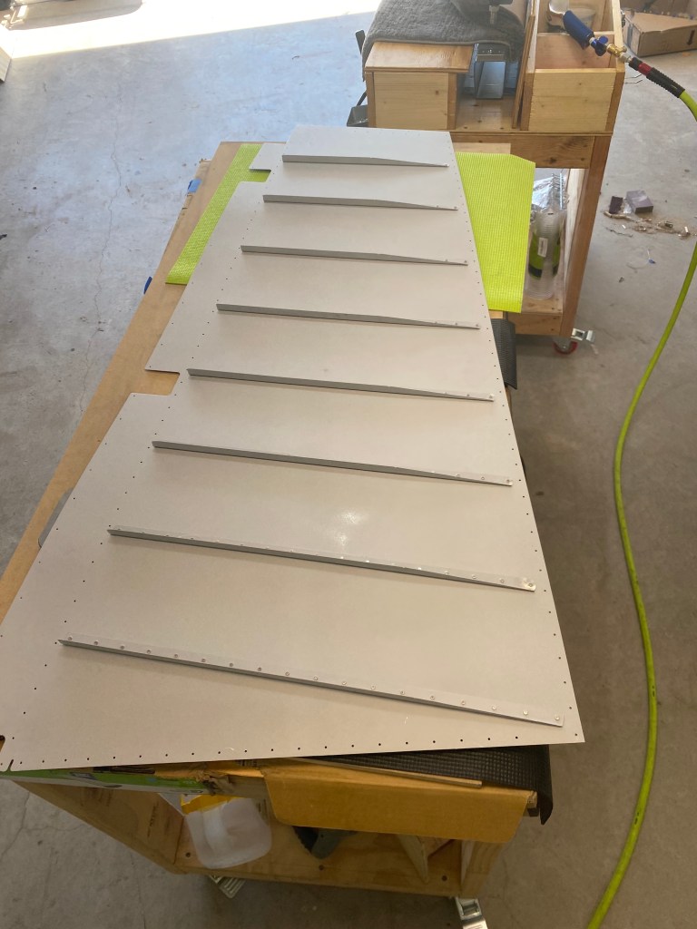
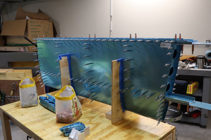
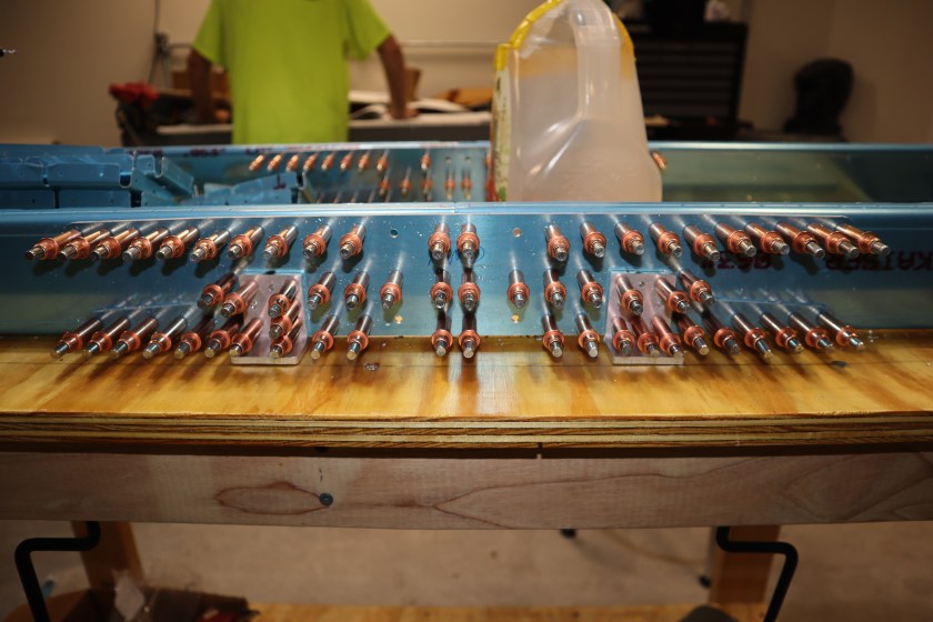
So after priming the next step is to rivet the rudder stiffeners to the skins. This is done using a technique called “back riveting”. To do this, special tape is used to hold the rivets in the hole, and then the outside of the skin is laid onto a large steel plate. The stiffener is then laid along the rivets, and you use the large plate as a bucking bar.
This seemed to be the easiest riveting so my dad and I tackled it first. For more on the first rivet, check out this post. There are eight stiffeners per side, and they range from 18 rivets to 11 rivets. In all, the riveting was fun. You are actually making an airplane part. This took most of the morning because we were stopping every rivet to inspect, and ensure they were airworthy.
In all we only drilled out one rivet from the skin. I had driven it off center and it did not set correctly. Overall very happy with the final product.
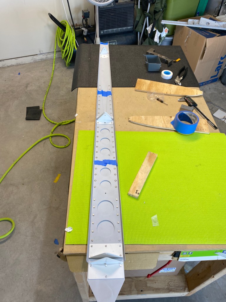
Now that the parts were primed, it was time to start riveting the vertical stabilizer together. This started with riveting the rear spar and spar doubler together. The Rudder attach brackets were riveted as well. Once the rear spar was riveted, the ribs were attached and the skeleton of the vertical stabilizer was riveted together to the front spar.
Next the skin was placed over this skeleton, and the skin was riveted to the ribs and front spar. Finally the rear spar was riveted to the ribs and skin. This completed the first major component of the airplane build.
Big day! I set the first rivet on the project. Luckily, my dad had come to town to help out. He is an A&P Mechanic (certified airplane mechanic) with his IA (Inspection Authorization). This means he is able to work and maintain certified aircraft. His years of experience provided validation and built confidence in my work.
The first rivet of the project was between the rudder skin and a stiffener. I chose this as the first set, as it seemed to be the easiest riveting I could do. Luckily, the rivet came out very well, and checks on the diameter and length verified it was an airworthy rivet.
So since I have a large batch of parts ready to prime, it was time to set up the sprayer and get priming. I started out by scuffing up all the parts for the horizontal and vertical stabilizers and the rudder. This will give the primer something to “hold too”.
The primer that I am using for the entire aircraft is Stewart Systems EcoPrime. This is a one part, water based primer. The reason I chose this primer is because it is non-toxic, and being one part, it is an easier process. Being in a neighborhood, it is important to me to be respectful of my neighbors, so being water based and non-toxic was a key factor.
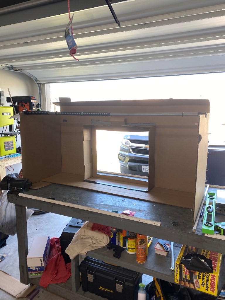
Next, I set up a spray “booth” from the cardboard box that the tail skins were delivered in. This booth helped to contain overspray and provide support for the bar which held the parts.
I was excited to start priming. It was another step forward. The more I primed, the better I got. I was able to work in batches, about an hour each. It took most of the day, but in the end, I was happy with my results.
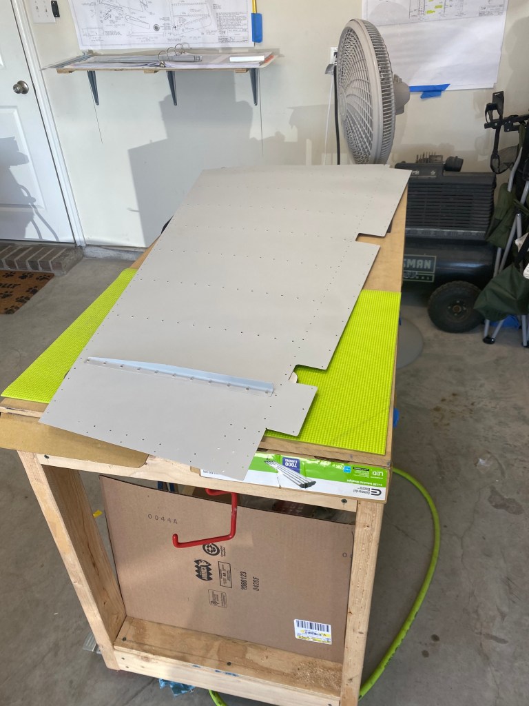
Now that the vertical stabilizer is ready for priming, the next step is to begin on the rudder. The first step is to take the provided stiffeners, cut them to length, shape the end, and match drill them to the skin.
After the stiffeners are match drilled, you debur and dimple the stiffeners and the skin. Then it is ready for priming.
Since I have to wait on priming the Horizontal Stabilizer (Horz. Stab.), I started to work on the Vertical Stabilizer (Vert. Stab.). The process is very similar to Horz. Stab. I started by clecoing the spar doubler to the rear spar. Next the rest of the assembly (ribs and front spar) are clecoed in place. Next all holes are match drilled to final size. This creates the skeleton of the Vert. Stab..
Just like before, the skin is then attached to the skeleton. After everything is clecoed together, the skin is match drilled to final size with the ribs and spars. Moments like this when an assembly is together is a very gratifying feeling. It’s a feeling of accomplishment and noticeable change. But this feeling is short lived, because you take it all apart and debur, dimple, and machine countersink the parts. Then it is ready for primer.
So, in the last post I discussed assembling the skeleton for the horizontal stabilizer. After the skeleton was disassembled and cleaned up, the structure was “rebuilt” inside the skin. The skin is the thin metal sheet that is the outside surface of the airplane. The skin is put into a jig that has a the contour of the horizontal stabilizer cut out. This helps to hold the shape while assembling the structure.
Once the skins are in the jig, I started adding the front ribs (aka nose ribs) to the skin with clecoes. Next, you add the front spar and cleco it to the nose ribs and the skin. You keep building inside the skin. Next up is the main ribs, and finally the rear spar.
After the everything is in place, the holes were match drilled to final sized. The entire process was completed for the left side, then it was disassembled, and the right side was completed the same way.
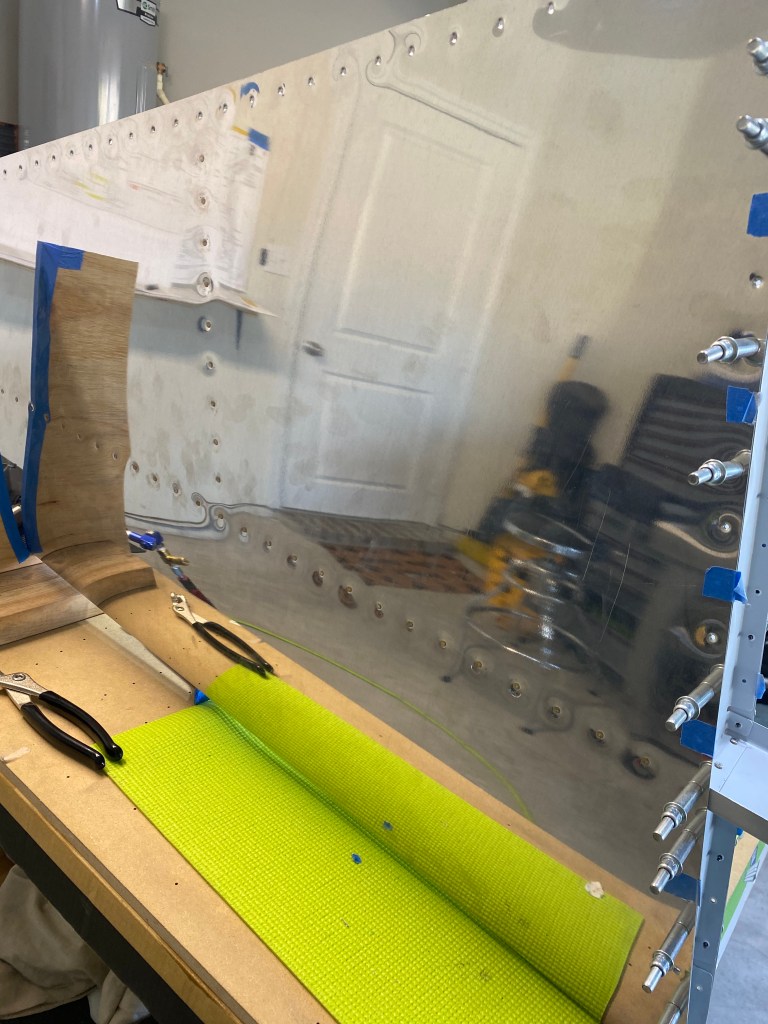
Once both sides were disassembled, it was time to start the final prep of the parts. The skins and ribs had to be dimpled. This refers to putting a small depression into the metal so that a rivet will sit flush once set. This is done with the DRDT-2 and the pneumatic squeezer.
The spars are too think to dimple, so they much be machine countersunk. This is completed by physically removing material with a cutter to create the small depression. The skin dimple will sit inside the machine countersunk depression.
So this is as far as I can go right now. I need to prime the parts, but weather is not cooperating. I will start work on the Vertical Stabilizer next.
The build has begun. But before I go into detail, it might be worth explaining some terms that I will use.
The first that comes to mind is “clecoing”. This is temporarily attaching two pieces of metal together using a specialized tool, called a cleco. The cleco is a spring loaded fastener that when compressed, can fit into a certain sized hole, and when uncompressed the cleco clamps the pieces of metal together. This is accomplished to ensure that parts fit properly together.
Another term that will be used is “matched drilled”. The kit came with most holes already drilled on all the parts. Because there could be small differences in parts, it is important to drill through all material to ensure the holes are exactly inline. In addition, most of the pre-punched holes are slightly smaller than the final hole size. To get the hole to the required size for the rivet, a builder mush drill to the final size. This is normally completed at the same time as match drilling.
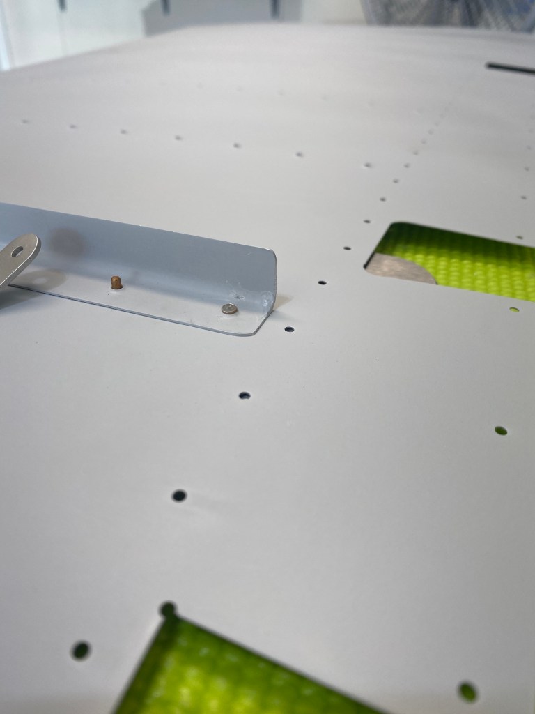
So, now that we have some terms in place, back to the build. I started by clecoing the front spar doubler to the front spar, then match and final drilling those holes. Following that, two attach brackets were manufactured out of angle aluminum stock.
Two attach brackets laid out on aluminum stock.
After those were fabricated, the rear spar doubler and rear spar were clecoed together, then match and final drilled. This was the start to the skeleton of the horizontal stabilizer. Then main ribs, pieces between the front and rear spar, and nose ribs, pieces on the front spar that face forward and shape the front of the stabilizer, were clecoed, matched and final drilled.
Next this structure was disassembled, and new final drilled holes and edges of the parts were cleaned up. Coming up in Part 2, we add a “skin” to the skeleton.
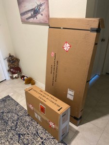
Great news, the empennage arrived a day early! This morning I checked the shipping status on my phone and noticed the it was “On the truck for Delivery”. The expected delivery date was still showing Monday, May 11th, so I did not think it would actually arrive. But I was wrong.
About 11:45 am the delivery truck was greeted by my dog barking at them. I heard a knock on the door, and when I opened it two boxes sat at my front door. I waived to the delivery driver as she got back in her truck, and I moved the boxes inside. After finished a few things inside, I moved the boxes to the garage for the grand opening, inventory, and organizing.
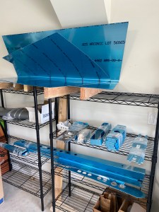
I decided to open the smaller of the two boxes first. I knew what I would find, but still, I was like a kid at Christmas! The first item I came across was the packing list, which listed out all of the parts, hardware, and materials that were included in the kit. Moving on, I was very impressed with how everything was packed. It was organized by sub kits which made the inventory much easier. I would grab a sub kit, open it, inventory it, re-wrap it, and then move it to shelves in my garage. This took a total of about 2.5 hrs, but it went quick and I was only missing one part.
I am still waiting for a few more tools to come in before I start the build. I also want to complete the practice surface kit, and the sheet metal basics kit that was included with the empennage kit. So stay tuned for more!
So my main workshop is the two car garage of my home. I have it set up with a large workbench, two smaller rolling workbenches, and one tool / dimpling cart. I was lucky to be gifted a large, multi shelf workbench from my father. It was too big for his current situation, but it worked perfectly for me. I also have two very mobile workbenches that are 2′ x 4′ and have locking casters. My thought was with a somewhat small space, versatility is important. So, I can put them next to each other and have a 4′ x 4′ cube, or 2′ x 8′ bench. Finally, I designed and built a tool cart to hold my most used tools and the DRDT-2 dimpler I intend to use. Again, versatility was important. I will include a separate post about the tool cart. It is 2′ x 2′ 4 1/2″ . Weird size, but check out the post to find out why.