The Rest of The Trim Tab

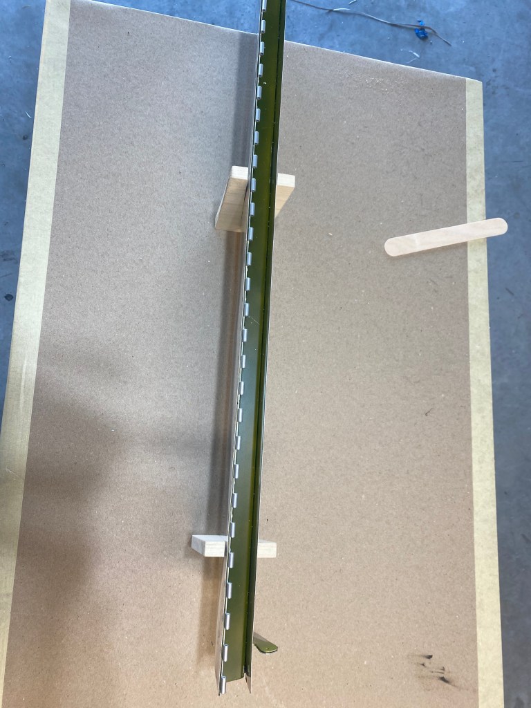
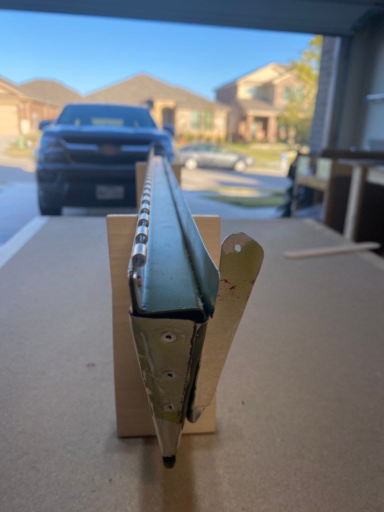
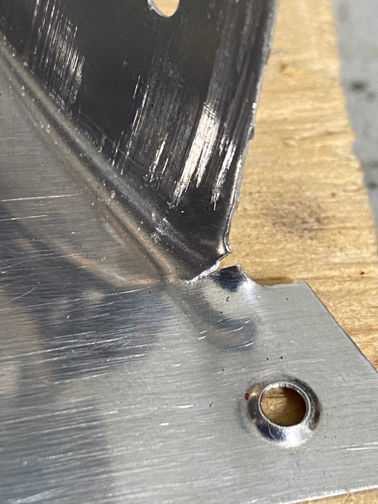
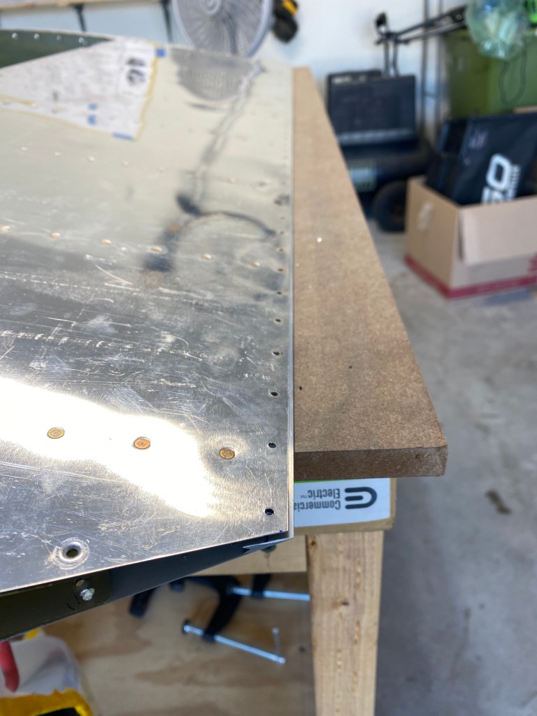
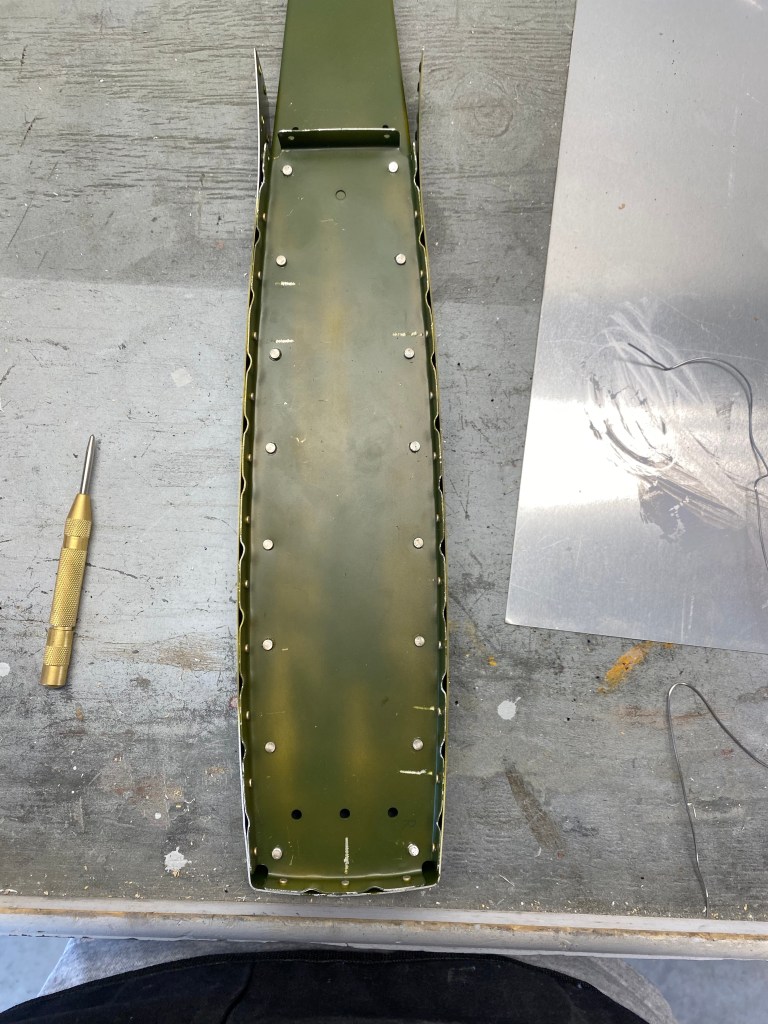
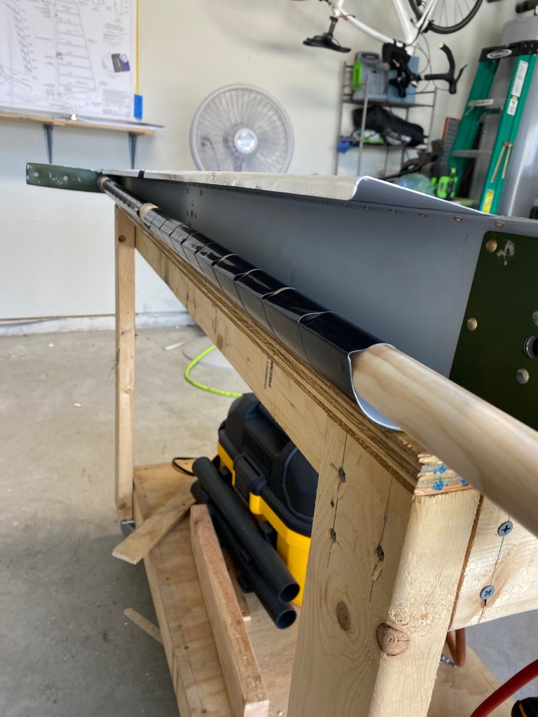
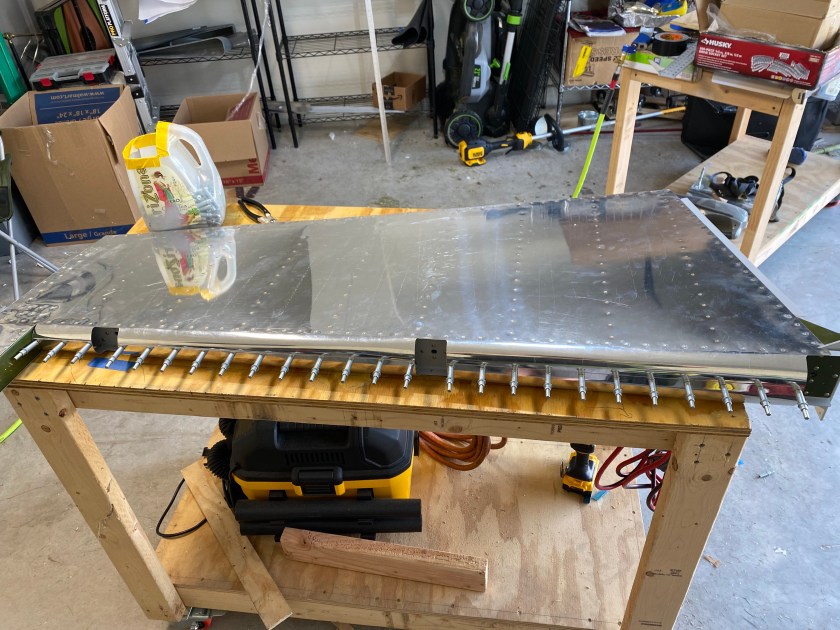
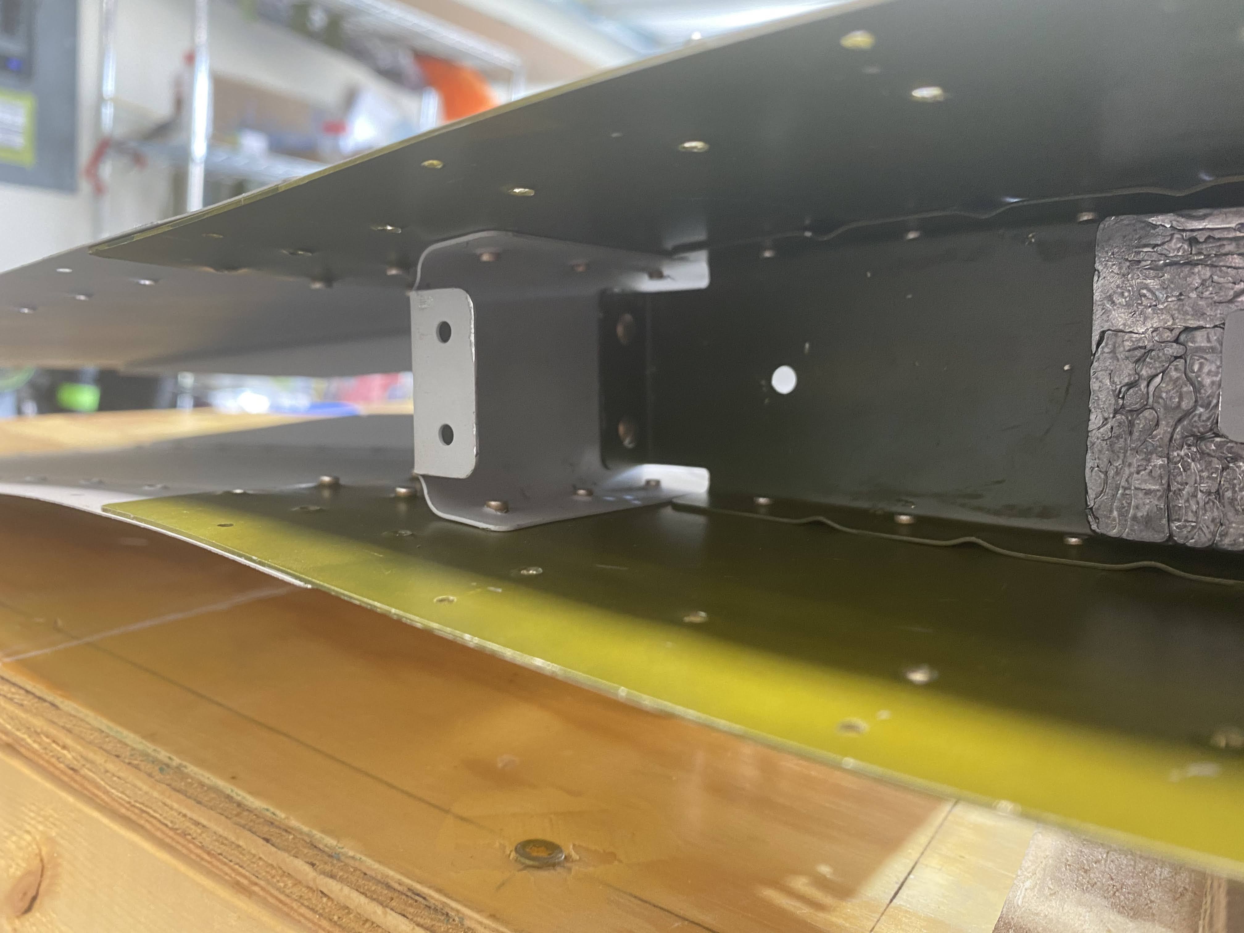
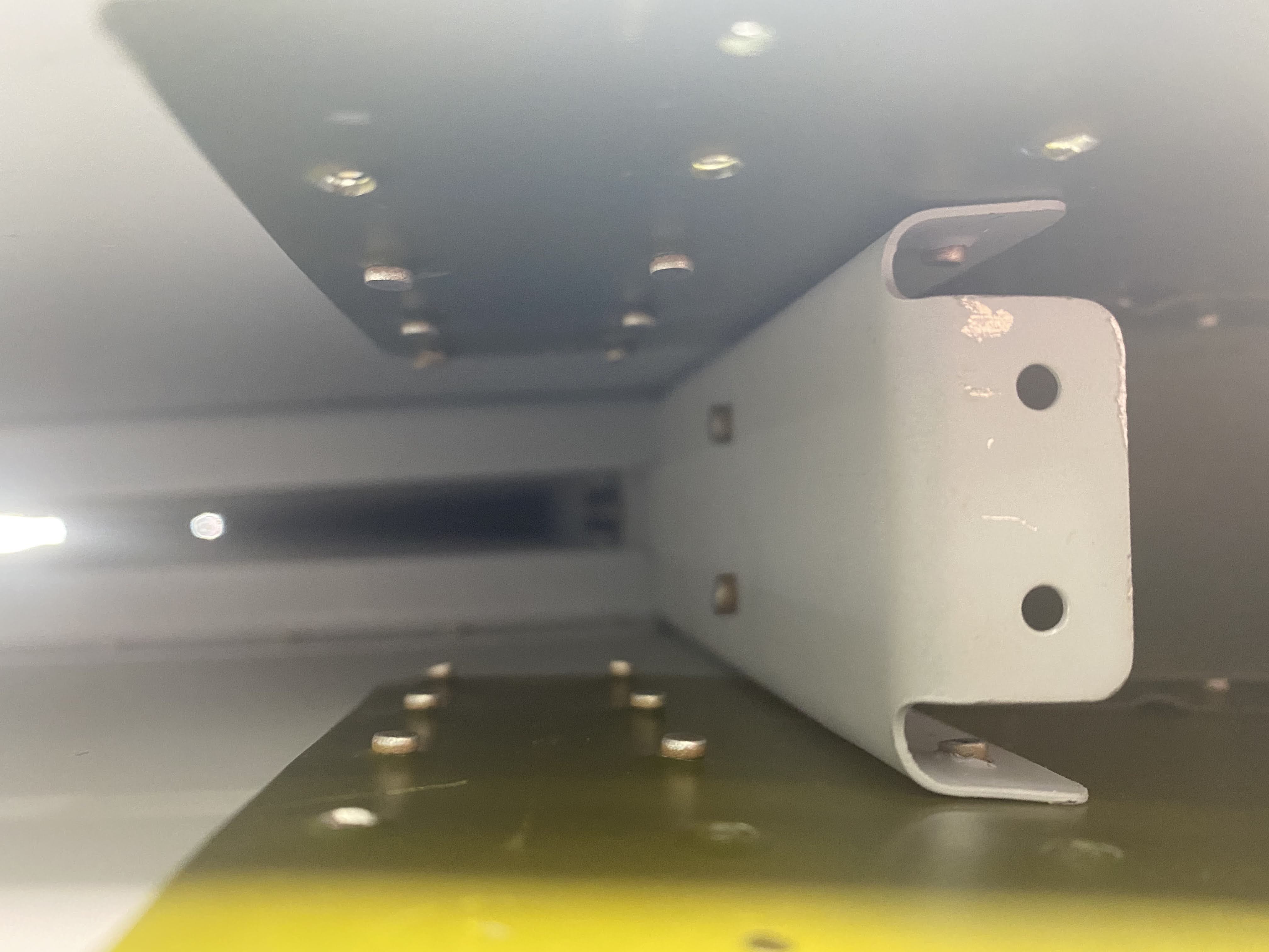
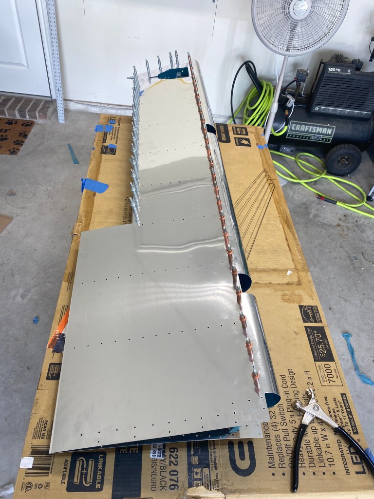
So, after the skin of the trim tab cracked, I decided to order a new skin. It was not worth the worry for just a few dollars. So, after a week or two the new skin arrived, and I picked up where I left off. Luckily the bend that broke the first skin is early in the process. This meant there was not much to do. So I got back to work match drilling the skin, spar, and attach brackets.

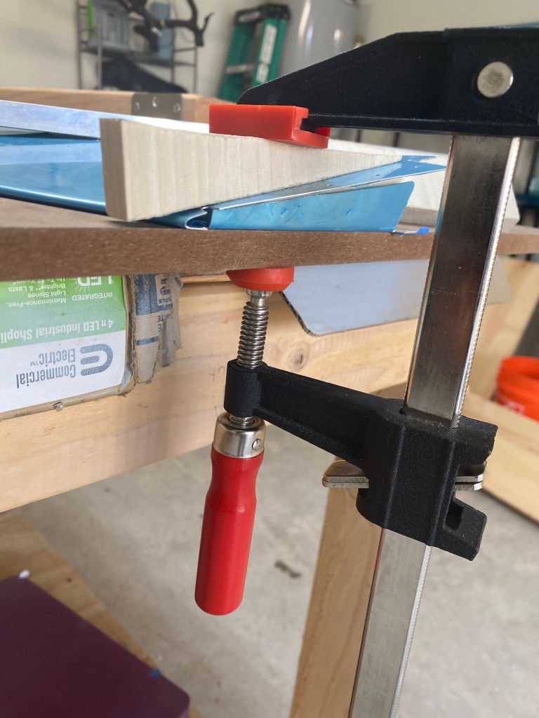
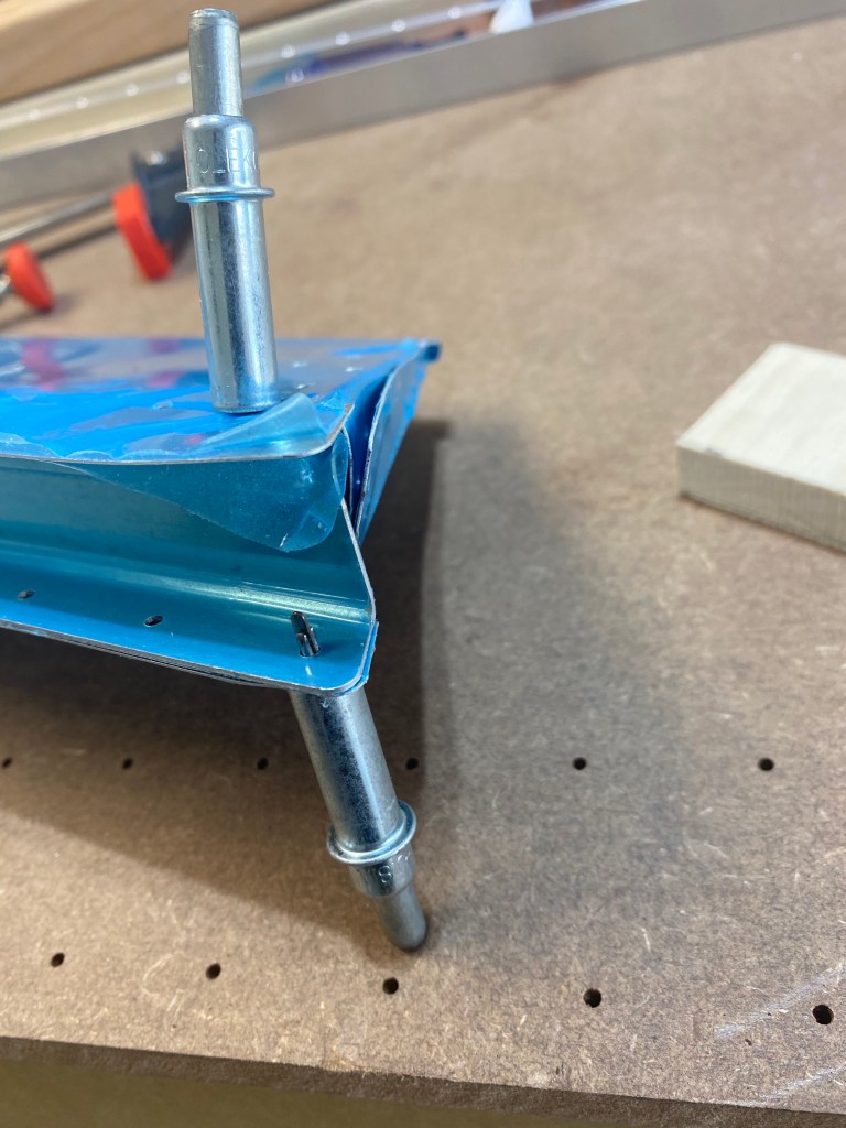
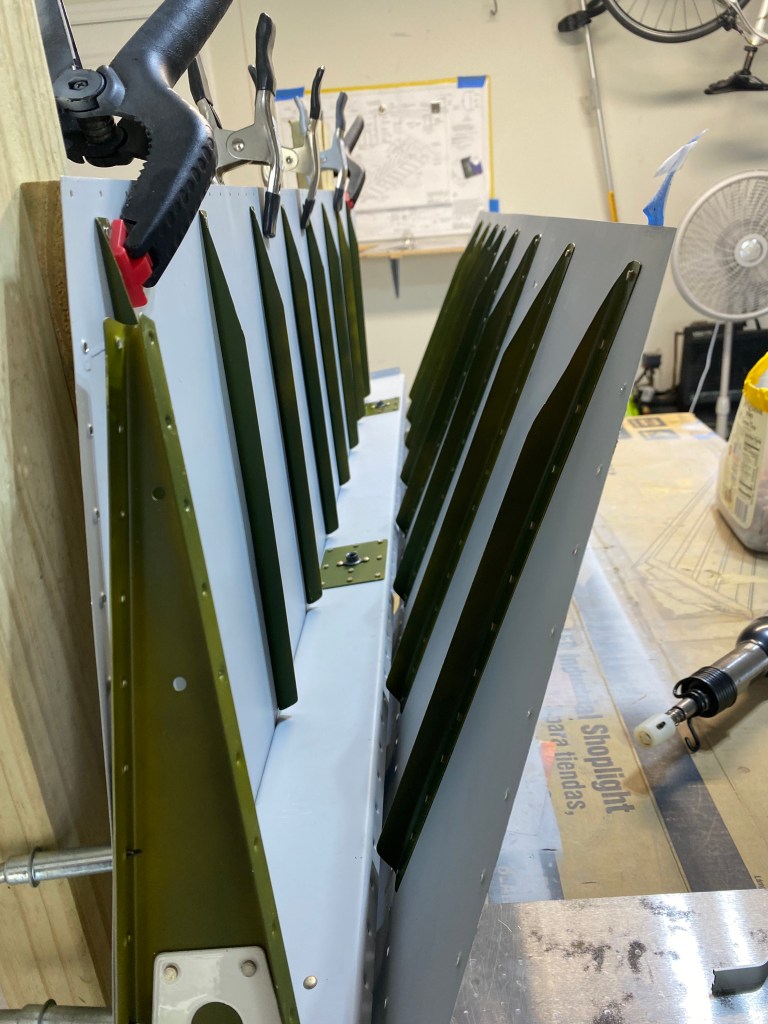
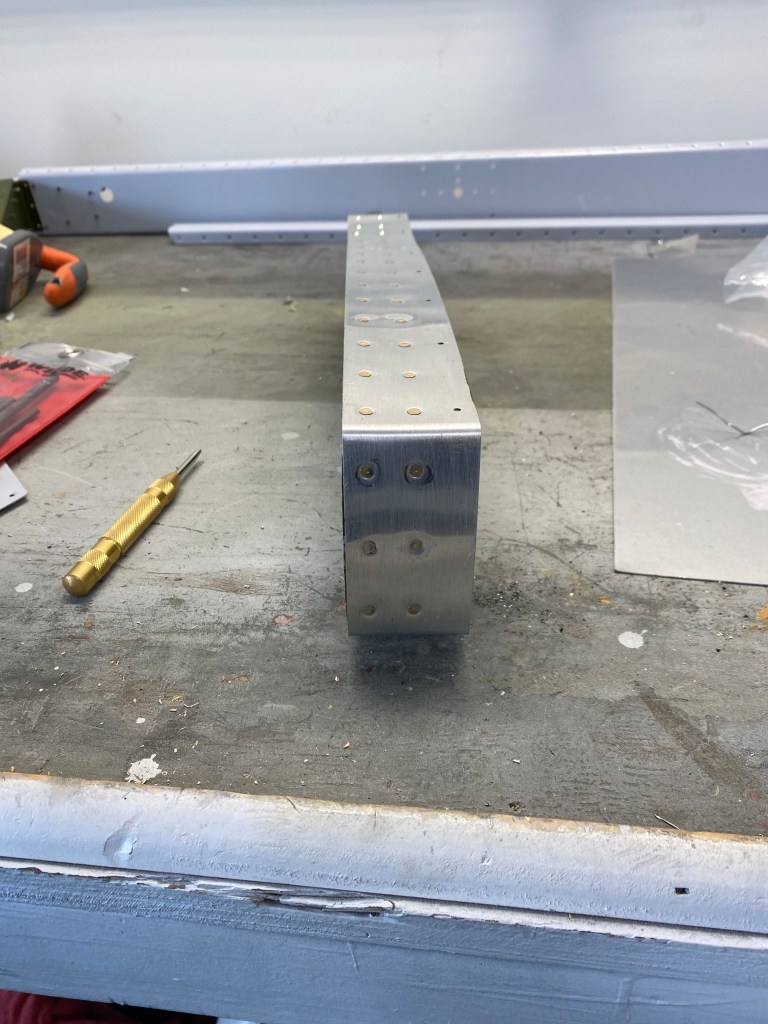
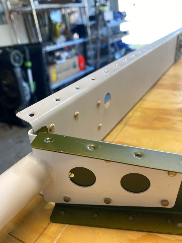
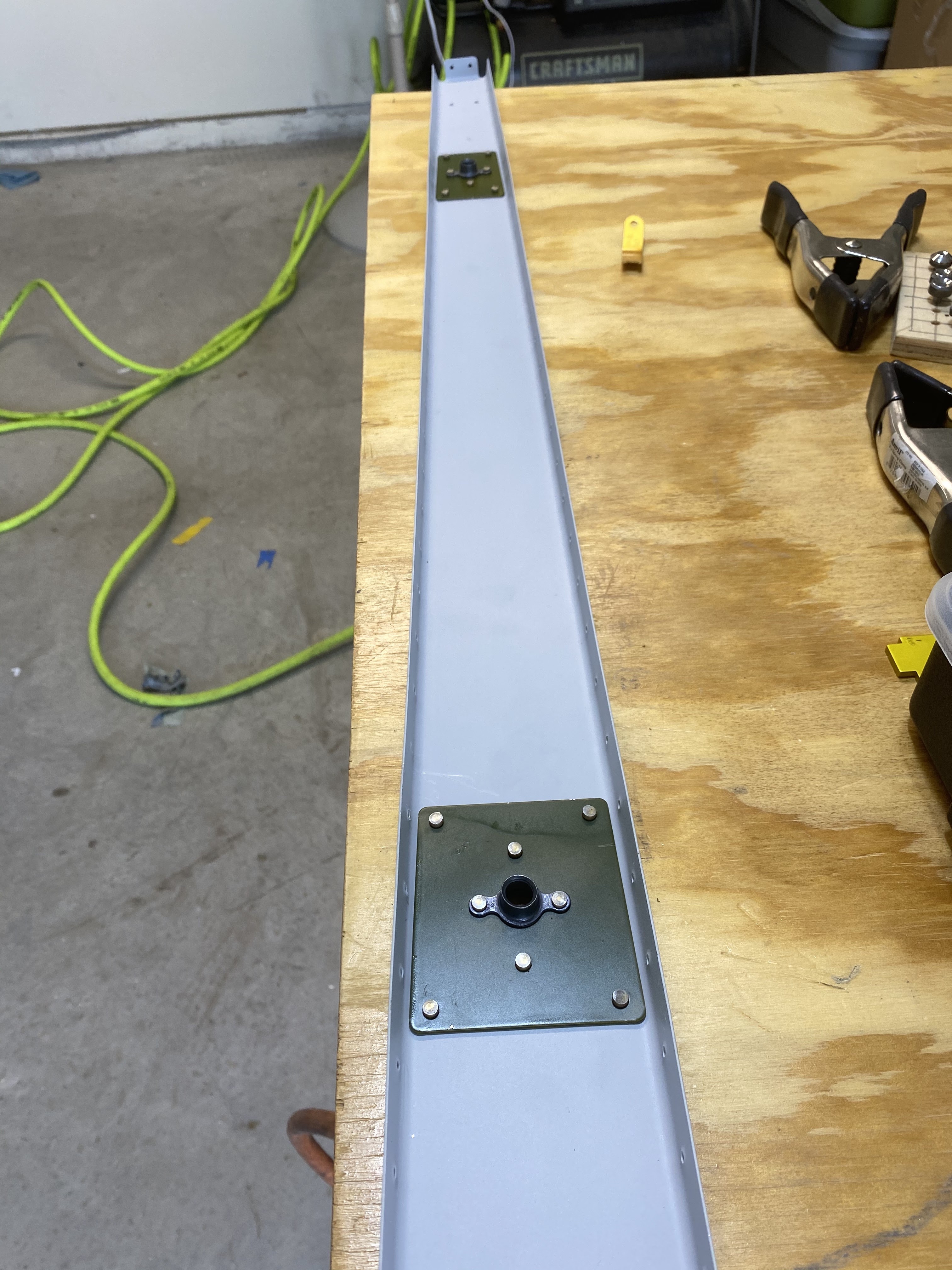
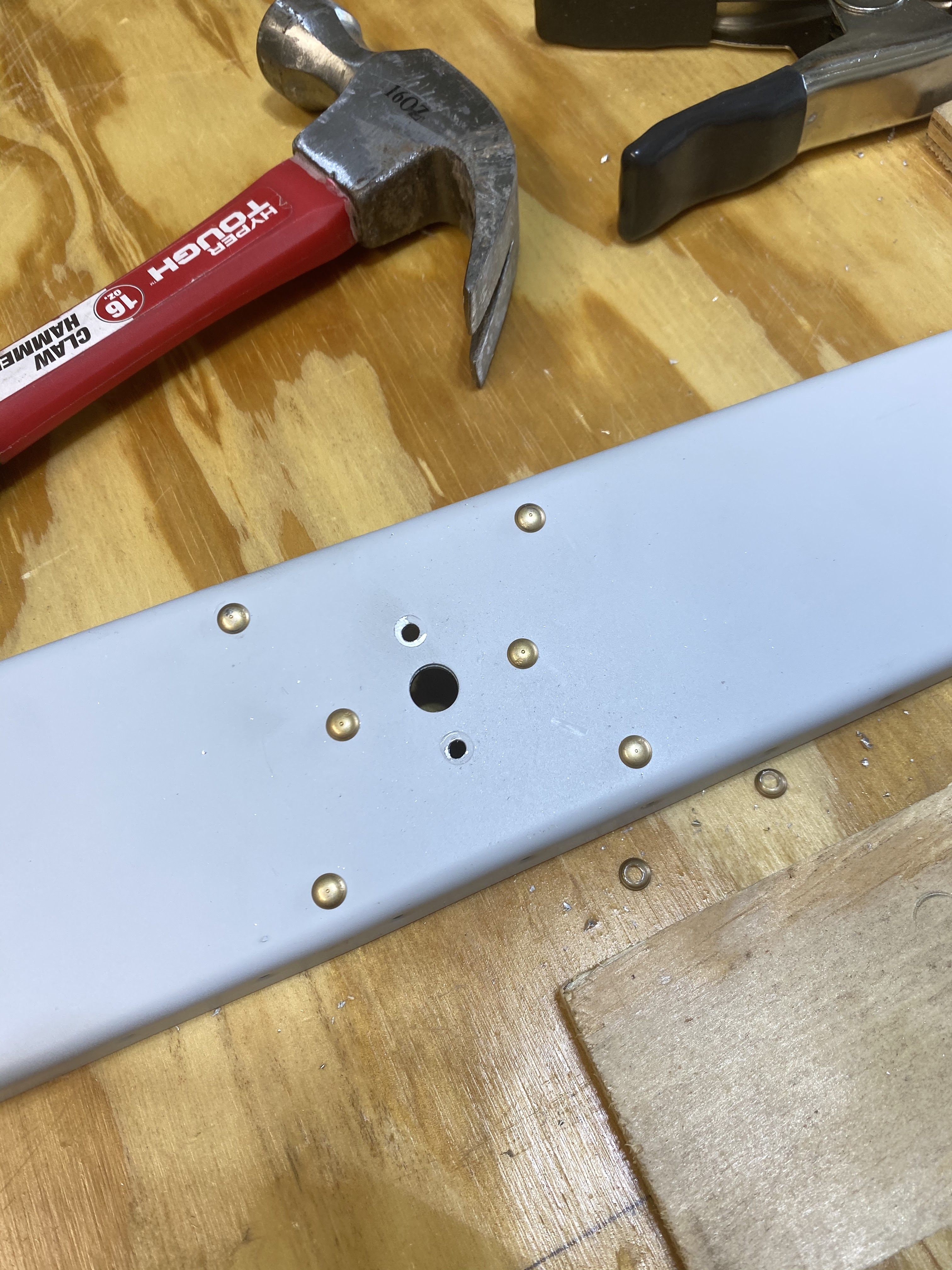
After this the parts were cleaned up and primed. I did not set up the large paint booth, instead, I used a rattle can primer. It was just easer. Finally, I rived all the parts together, and matched the tab to the elevator. This was it for the tail kit. Now to move on to the wings!

The Elevator Trim Tab

The elevator trim tab sits on the left elevator and is used to relieve control stick forces. The tab has two foam ribs to maintain the structure. After the foam ribs are fitted to the tab, the ends are bent and match drilled.

My first attempt was not the best. I practiced on some scraps, but lost everything I had learned when I began on the real thing. I tried to unbend it so I could try again, but when I did, the skin cracked. This made the decision to use this piece pretty easy. Time to order a new one.

Elevator Riveting 1

So now that all the parts are match drilled, we can begin riveting the parts together. I started with the counterbalance arms. Both left and right were fairly easy.

Next, I added the attach doublers to the elevator spar. This time, I was super extra careful to make sure that the plates were on the correct side of the spar. I also attached the elevator control arm and the end rib.

After the skeleton was riveted together, the spar was riveted to the skin. This was difficult and required two people. I opened the skin up and set it on it’s side.

Rudder 5: Finishing Up

So, the next item up is the trailing edge of the Rudder. This consists of the skins being bonded to wedge and then riveted together. Both skins are dimpled to get a smooth finish, so the wedge has to be countersunk on both sides. This was a new technique for me, but after a little practice, I got the hang of it.

Next up, the wedge is placed between the skins, and bonded using a two part sealant. The edge is then attached to a piece of angled aluminum. This helps to set the trailing edge straight.

After letting the sealant set for a few days, you then rivet the trailing edge together. Overall, I’m very happy with the trailing edge. Only thing left is to roll the leading edge.

The last item to complete for the rudder is the roll the leading edge. This was not as difficult as I had thought. You get a one inch diameter dowel rod, tape it to the skin, and then roll the skin. It took a surprising amount of force, but I got it bent. Then I match drilled the holes, demurred them, and then pop riveted them together. This marks the completion of the rudder (until I do the fiberglass tips.).

Rudder 4: Riveting the Rudder

After making my rudder mistake, click here to read more about it, it took about a week and a half to get the part and catch back up to where I was. I started by riveting the reenforcement plates onto the rudder spar, correctly this time.

After this the lower rib, reenforcement plate, and the rudder horn were riveted to the spar.

Next the counterbalance rib was riveted to the counter balance skin, and the counterbalance weight was attached. Then this assembly was riveted to the rudder spar as well.

Then the rudder skins where clecoed to the rudder spar and the counterbalance skin was riveted to the other skins. This took a combination of different riveting techniques to get all of the rivets set. After this was completed, the skin was riveted to the spar and the lower rib.

Finally the top rib was riveted into place, but I forgot to take pictures of this. Next up will be working on the trailing edge of the rudder.

First Major Mistake

So, after the priming was complete, it is time to start final assembly of the rudder. The first parts assembled on the rudder are several reenforcement plates that hold the hardware that attach the rudder to the vertical stabilizer. I referenced the plans and started to rivet the parts together. After riveting two of the three plates, I recognized that I had made a mistake. Below is a picture of what I did.

The mistake is the those green plates should be both the other side of the gray piece. I did not double check the drawing and confused which side of the gray spar the plates should be on. So, to correct this, I had to drill out all of the rivets, move the plates to the back, and then re-rivet the plates to the spar.

This would be super simple, except while drilling out the rivets, some of the holes became enlarged. Since this is a crucial part, I decided to reorder the parts from Van’s Aircraft and try again.

A valuable lesson was learned: double check the plans before riveting something together. A simple glance at the plans would have caught my mistake and saved me the time lost redoing work I had already completed.

Left Elevator

So far, the left and right elevators have been very similar. But now, there are some differences. This is because the trim tab is on the left elevator. The trim tab helps to relieve pressure on the control stick. This trim tab means some extra structure to support a hinge so that tab can move. So, instead of a continuous trailing edge, the left elevator has a small trailing edge, and then a channel where the hinge attaches the elevator to the trim tab. So like all other structure, the channel is clecoed and match drilled to the skin.

Elevator Skeleton

Now that the skins have their stiffeners, it is time to build up the skeleton for the elevators. The first step is to cleco and match drill the reinforcement plates to the spar. These reinforcement plates are where hardware will be bolted to connect the elevators to the horizontal stabilizer. Next, the end rib is clecoed and match drilled to the spar. this intersection is where the elevator horn is riveted to the elevator. This horn will control the movement of the elevator.

Once the skeleton is together, the skin can be clecoed and match drilled to the spar. Then the counterbalance arms are clecoed together, and those are added to the structure and match drilled.