Now that the tanks are finished, time to rivet the leading edges so they can be added to the spars. Most of the work was already completed before the leading edges were primed. They were just clecoed back in place, and then riveted. This went pretty easily, and next it is on to putting the tanks and leading edges on the wing spar.
So next was putting the tanks and leading edges on the main spar. First the leading edge goes on. Then the tank is added. This helps to ensure there is no sag in the spar when the main skins go on.
This is super exciting! Great progress, even though it is hot outside in Texas now. it really starts to look like a part of an airplane now. Next will be the main wings skins.
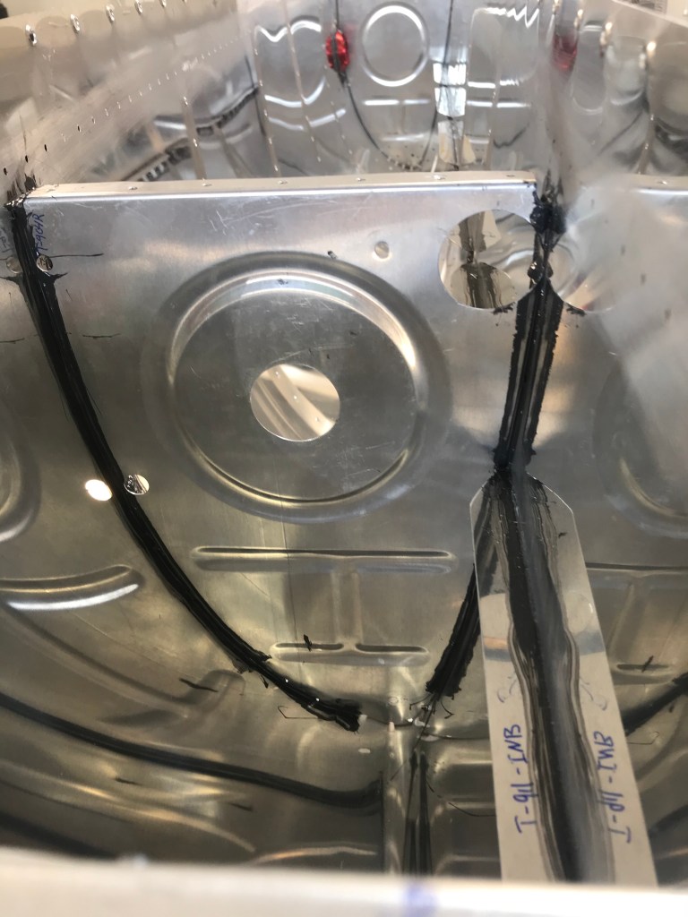
So the tank was almost ready for testing. The last major part to put on was the back baffle. This is really tricky because there are several ribs which all have to line up. Once everything is lined up, the side of the baffle is riveted to the tank skin.
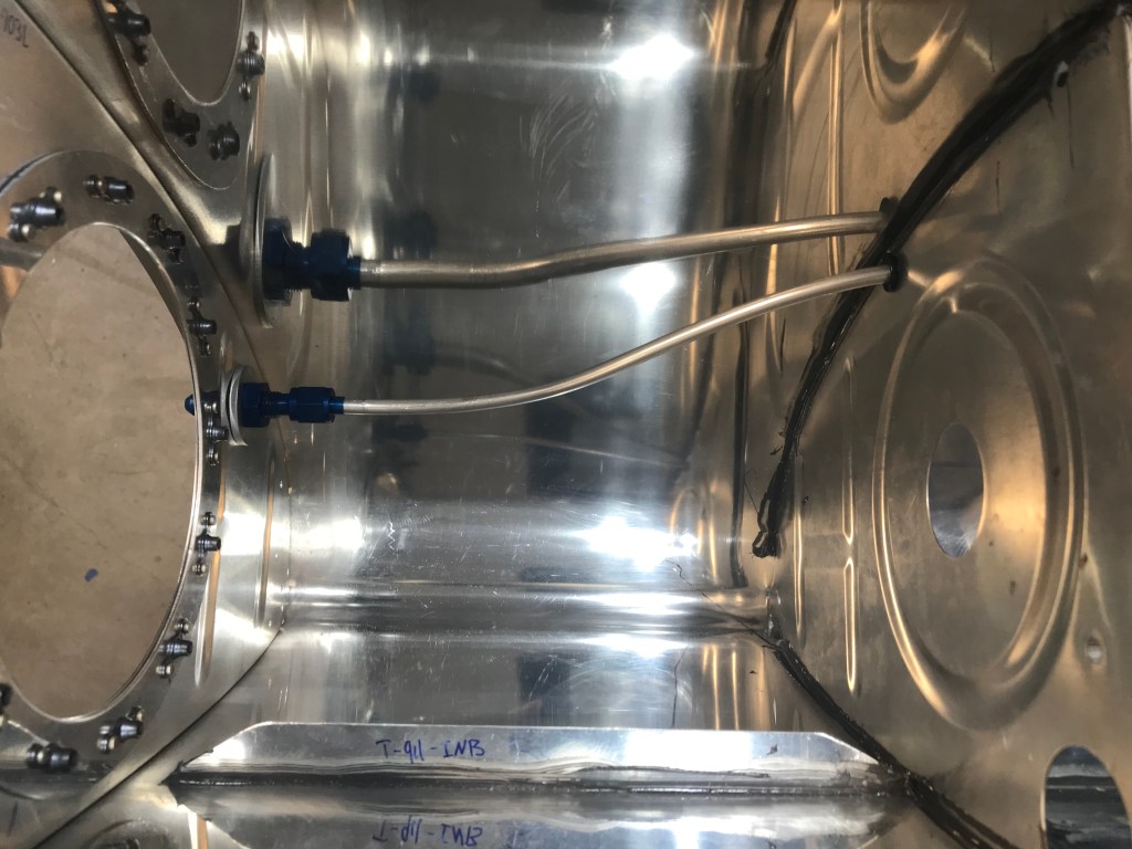
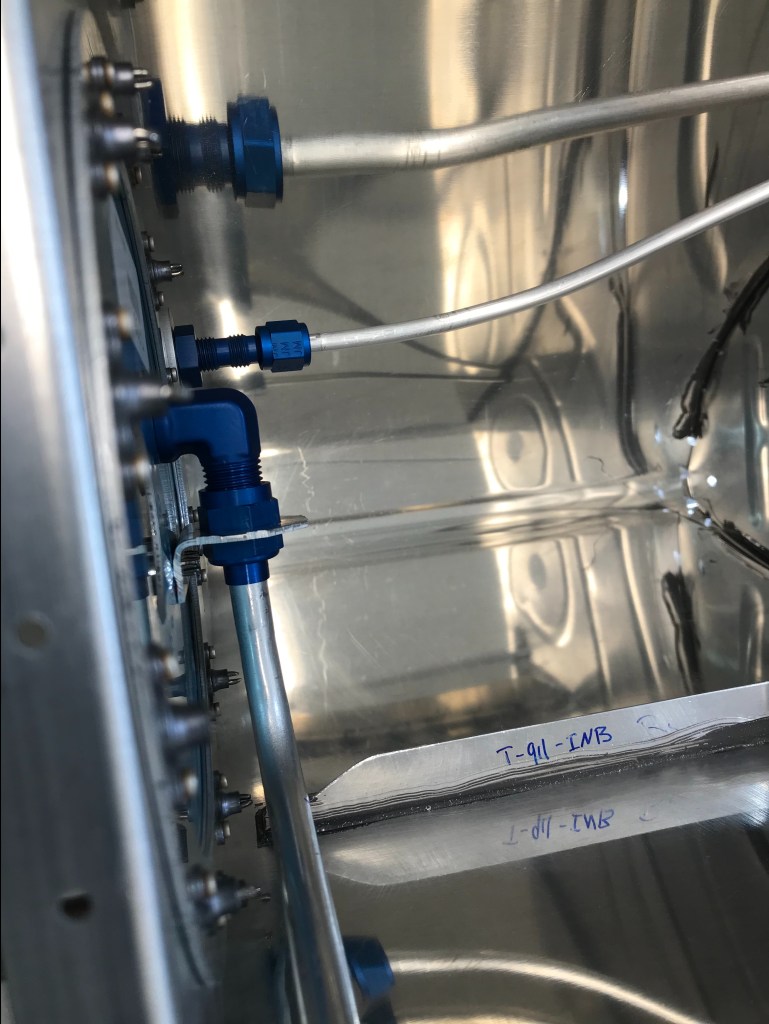
The last step was to add the tank attach brackets to the back of the baffle. This is done with pull rivets since you cannot access the inside of the tank very easily. Now the structure of the tank is complete. Time to close out the last few items. This included the plumbing for the fuel vent and fuel pickup, and the access plate.
Once this was completed, it is time to test the tank. I ordered the test kit from Van’s. After testing there was only two leaks on one tank, and no leaks on the other. Overall, very happy with how it turned out!
So now that the all the drilling and dimpling work is finished on the tank, it is time to put it together. Because the tank needs to be water-tight, sealant is used to achieve that. It is a two part sealant that has to mixed at a ratio of 10:1. This stuff stinks, and is super sticky! A thin coat of sealant is applied to parts prior to riveting. Then a nice fillet is applied around the parts, and all of the rivets are incapsulated to prevent fuel from leaking out. The goal is to seal the tank from the inside out. First to be install were the filler neck, drain flange, and the stiffeners.
Next was time for the actual ribs of the tank. Again sealant was used to to ensure a water-tight seal. But you have to be careful, because if you use too much sealant, you can alter the shape of the tank, and it may not fit correctly. So I think this is more of an art form than a science. But in the end, I got through it. I’m sure its on the neatest job, but the most important question is will it leak?
Now I will not know if the tank will leak until it cures completely. That may take an additional 2-3 weeks from today (04/18/2021). I will for sure update the status when I know it. With all the ribs in, there are a few more items to take care of in the tank. The first is the vent line. This ensures that there is not a suction on the tank. Additionally, the fuel pickup tube is added to the tank. Finally, the Fuel Level Senders is added as well. Now to get the other tank to this point.
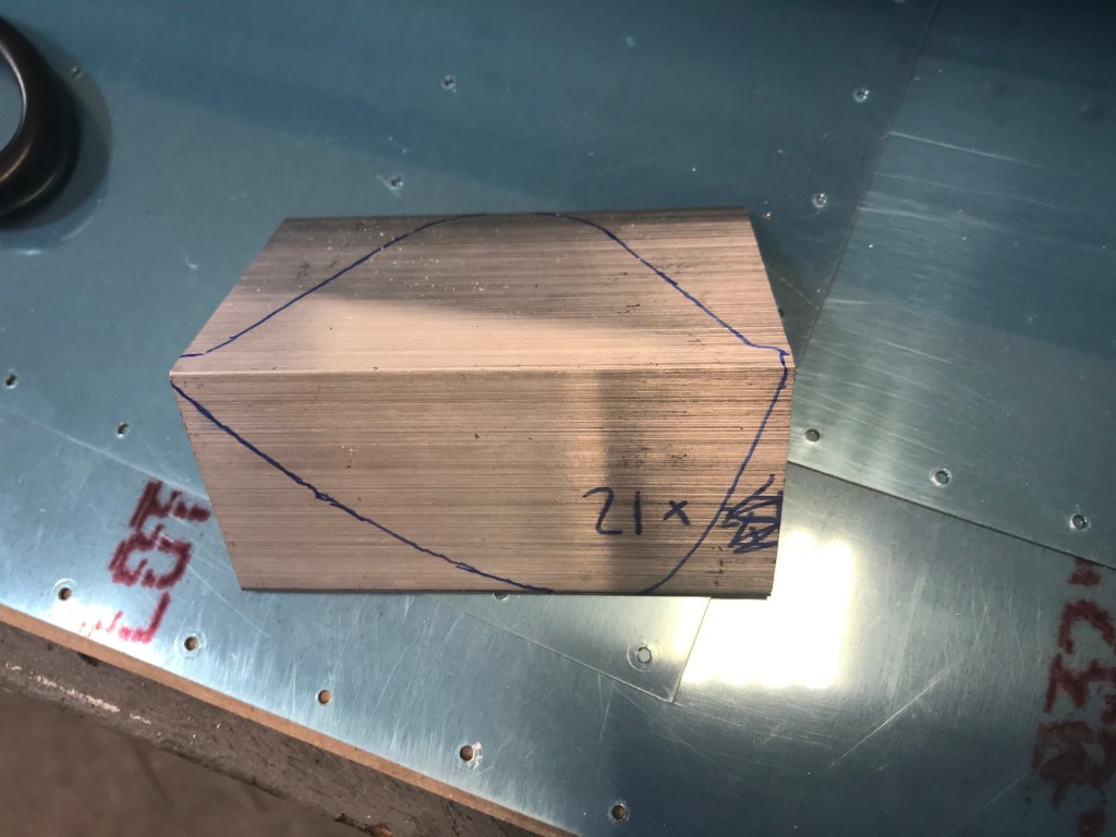
Now that the tanks have been fitted, there are a few more pieces that need to be made for the tank. The first is the Tank Attach Bracket. This piece will attach the tank to the fuselage of the airplane. It helps to distribute the weight. It starts out with a piece of angle aluminum (Looks like an “L”). I used a templed included with the instructions to trace it onto the aluminum and then used a band saw to cut it out.
Then, using the same pattern, I drilled several holes as instructed. Finally, the bracket is match drilled to the rib. It is key to remember where your fingers are. I nearly drilled my finger while match drilling. Luckily, it barely grazed my finger, but I started paying attention a lot more.
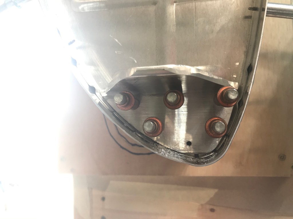
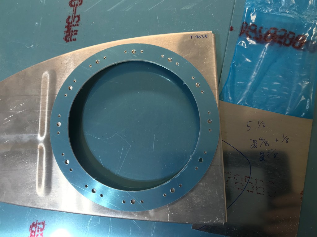
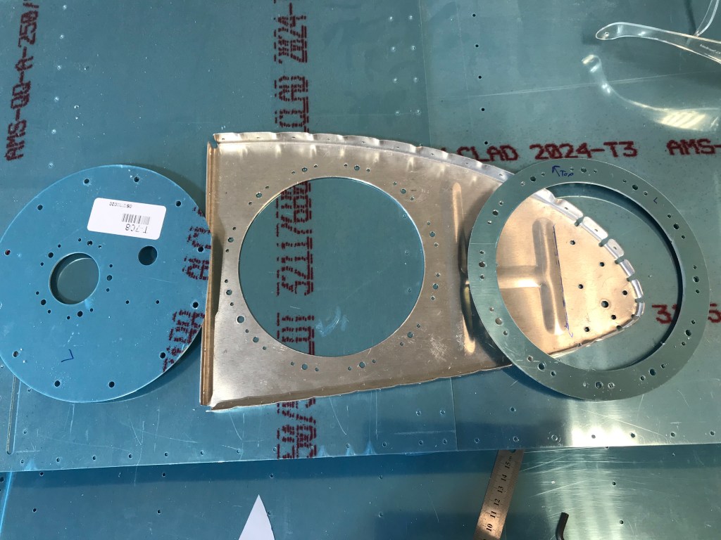
Next up is a modification to the inboard rib of the tank. It comes as a solid piece of metal. A large hole is cut out of it, and a doubler ring and special cover is used to cover the hole. The doubler ring allows for nut plates to be attached to hold on the cover. The cover holds two important items.
First, it holds the fuel level sender. This lets the pilot know how much fuel is in the tank. Secondly, it holds the fitting for the fuel pickup tube. This takes fuel from the tank, and attaches it to the fuel line from the fuselage.
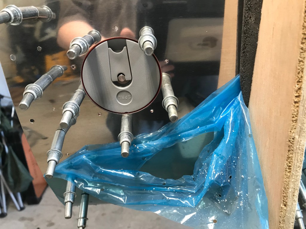
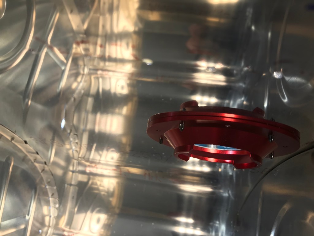
The final two things I will cover are the fuel cap and drain valve. Not a lot of anything going on here. Parts are already made, just match drill them to the skin. I will say that the fuel cap piece had a cool feature. When it was designed, the lip around the cap holder, was designed to be different thicknesses. This is to account for the bend in the fuel tank skin. So you can see that in the middle picture, the thickness changes as you go around the lip.
Finally the drain valve is used to drain the tanks if it is ever needed. This also is the lowest point of the tank. Aviation fuel is less dense than water, so the water will sink to the bottom, and thus the lowest point of the tank. Part of the pre-flight check is to take a sample from each tank to ensure that no water has contaminated the fuel.
Up next, we start to rivet the tank, and I will talk about my new “best friend”, tank sealant.
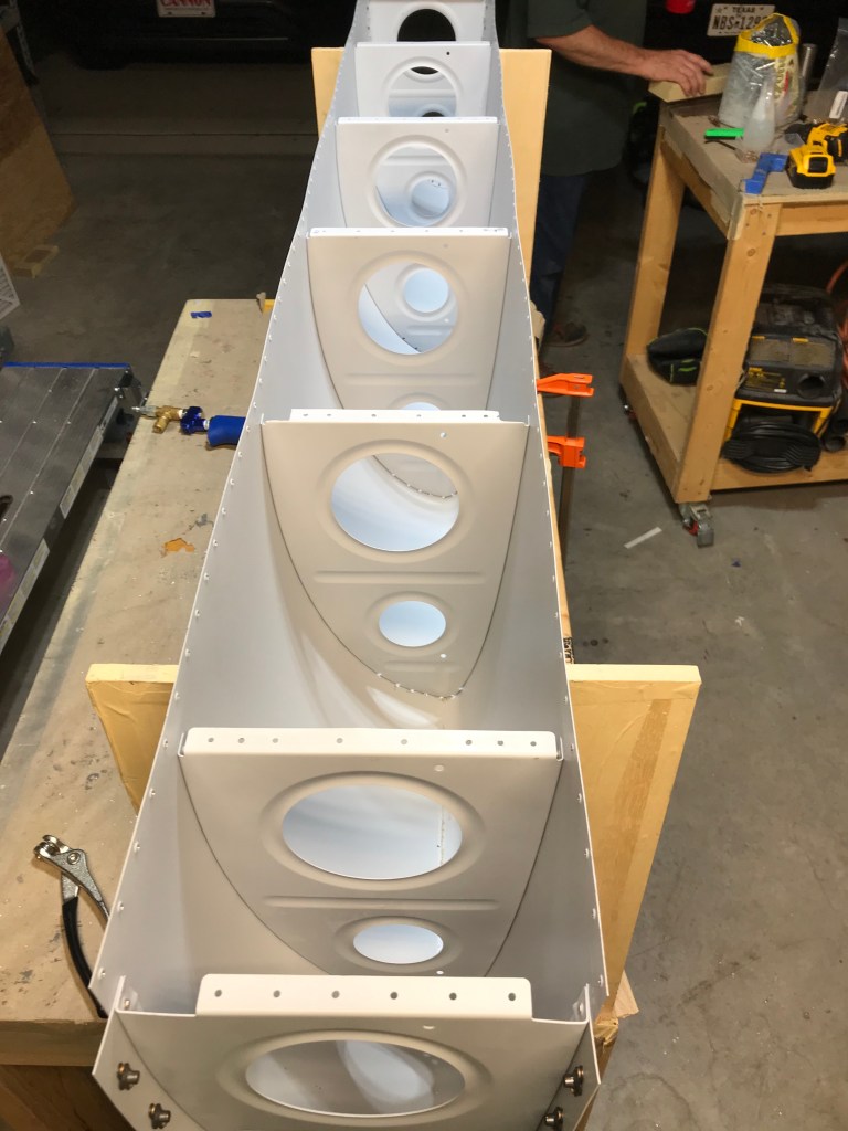
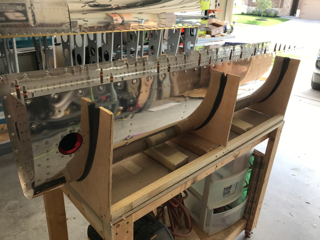
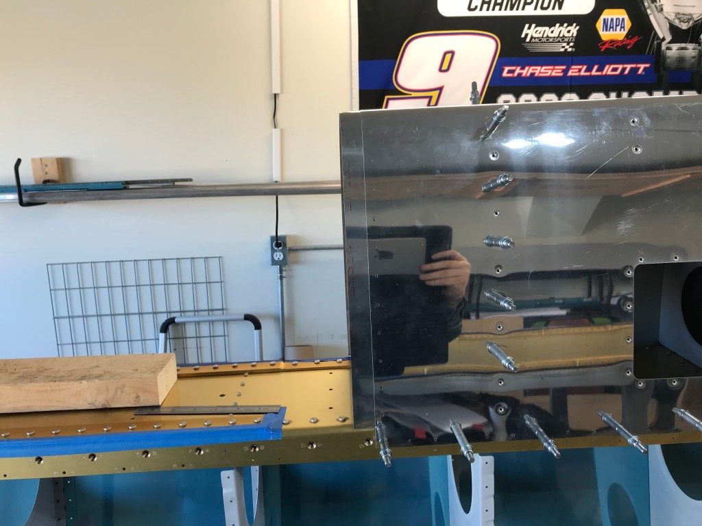
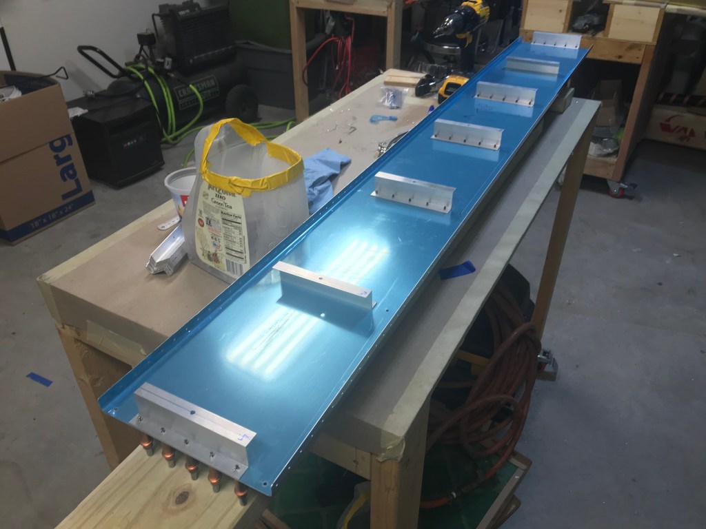
So, now that we have the structure together and the skins on the it, the time has come to fit the fuel tanks and the leading edges. This is the first time that I really got an understanding for how the wing will look and the size. I was surprised. The first step was to attach the leading edge to the spar. this is done by attaching the ribs of the leading edge to the web of the spar (photo one below). Once in place and secured, a splice strip allows the tank to be screwed into it. This means the tank will be screwed into the leading edge.
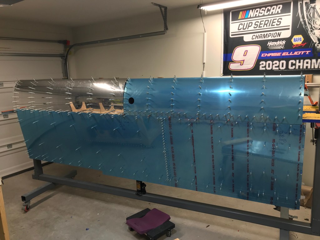
After leading edge was on, the tank is fitted. It is secured to the spar. Below are pictures of the left wing with both the tank and leading edges on. Big accomplishment.
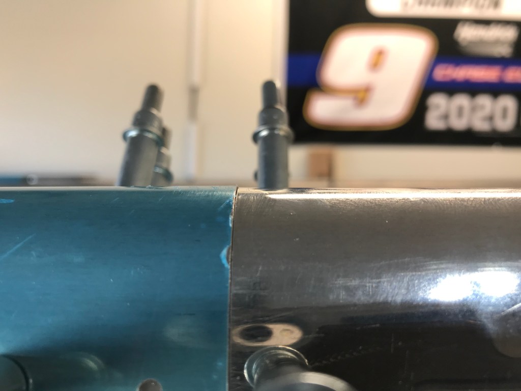
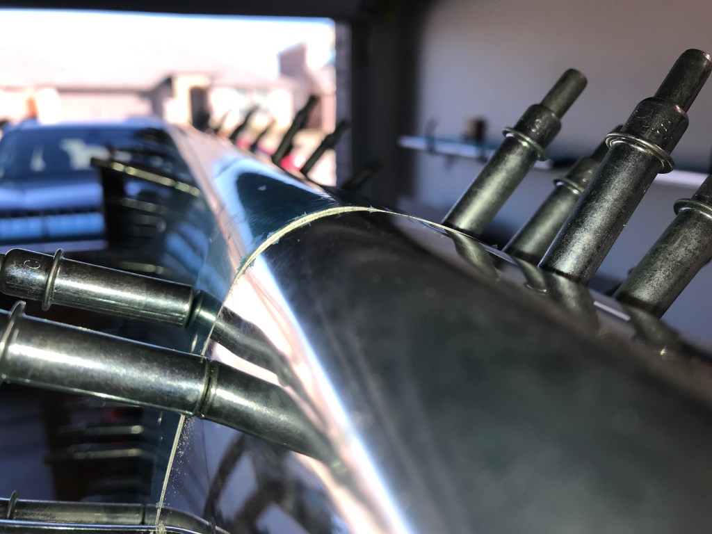
One big factor is how well these two parts line up. They are both made off the wing, and at this point, it would be very difficult to change the shape. Luckily, both the left and the right sets line up very closely, and I deemed it acceptable.
The last little step in attaching the tank for fit, is to drill the attach holes into the “Z” attach brackets. Since you want these to fit perfectly, the center (of three) holes is drilled before going on the spar, but once there the other two are matched drilled. This ensures a perfect fit. Next up will be more fuel tank work!
So similarly to the leading edges, the fuel tanks have a skin that is held in shape by a set of internal ribs. There are a few differences between the two. The first is the fuel tanks have additional stiffeners along the bottom of the skins. This are very similar to what was made and used on the rudder and elevators. Next, the ribs have a cutout on the bottom corners. This is to allow fuel to drain to the pickup so it can go to the engine, and it also allows water to drain to the lowest point, which has a quick drain. This drain is checked before every flight to ensure no water is in the fuel. The rest of the assembly went together just like the leading edge.
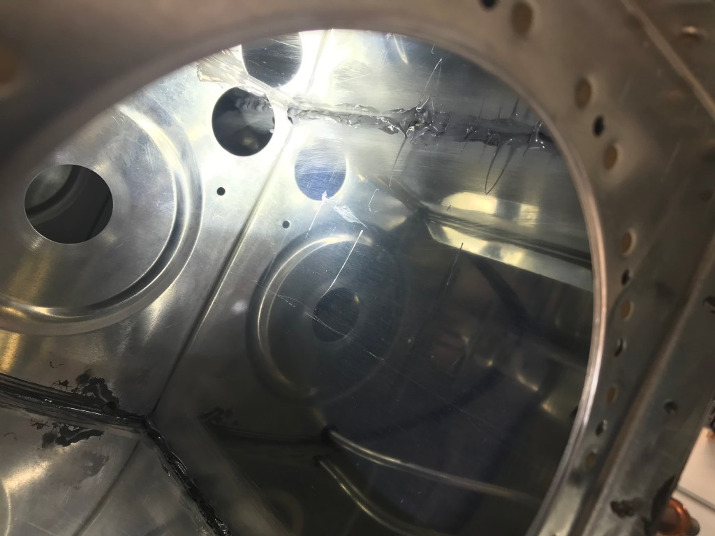
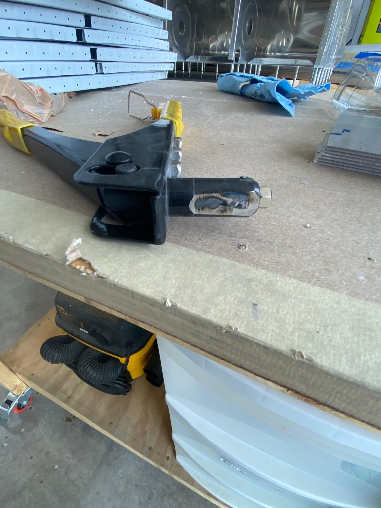
Since the leading edge ribs attach directly to the spar, the fuel tank has to have a back baffle to help create a water-tight tank. The baffle has attach brackets which attach the baffle and tank to the spar. These are made from a “Z” channel that is supplied. Once the tank is together, the attach brackets are temporarily attached to the baffle with blind rivets. The issue is the web of the channel is so close, most rivet pullers do not fit into the area. So, a quick trip to a local tool shop resulted in an inexpensive rivet puller. It was then ground down with a grinding wheel until it fit, and it still functioned! This was then used to pull the rivets, and finish this part of the tank build.
Also, I’m trying something new. I’ve been saving time-lapses of my work to help prove to the FAA that I am the primary builder of this airplane. I have put several parts together in videos, and I plan to start sharing them with the blog posts. So feel free to check them out.