Fitting Leading Edges and Tanks

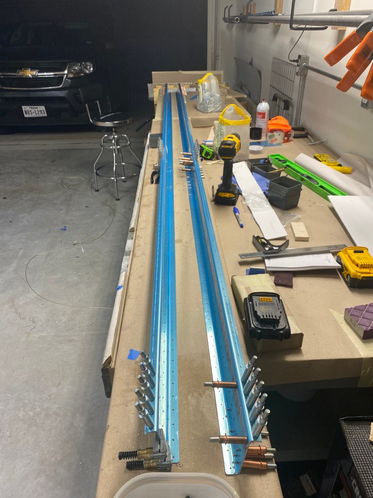
So, now that we have the structure together and the skins on the it, the time has come to fit the fuel tanks and the leading edges. This is the first time that I really got an understanding for how the wing will look and the size. I was surprised. The first step was to attach the leading edge to the spar. this is done by attaching the ribs of the leading edge to the web of the spar (photo one below). Once in place and secured, a splice strip allows the tank to be screwed into it. This means the tank will be screwed into the leading edge.

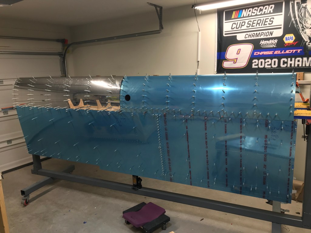
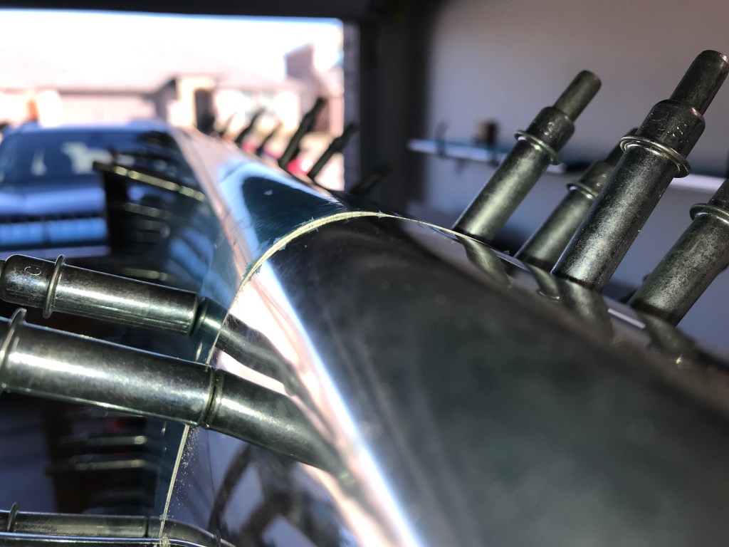
After leading edge was on, the tank is fitted. It is secured to the spar. Below are pictures of the left wing with both the tank and leading edges on. Big accomplishment.

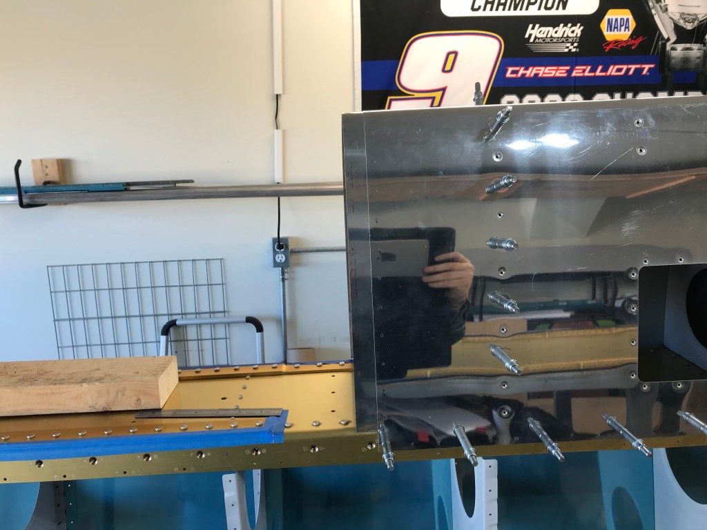
One big factor is how well these two parts line up. They are both made off the wing, and at this point, it would be very difficult to change the shape. Luckily, both the left and the right sets line up very closely, and I deemed it acceptable.

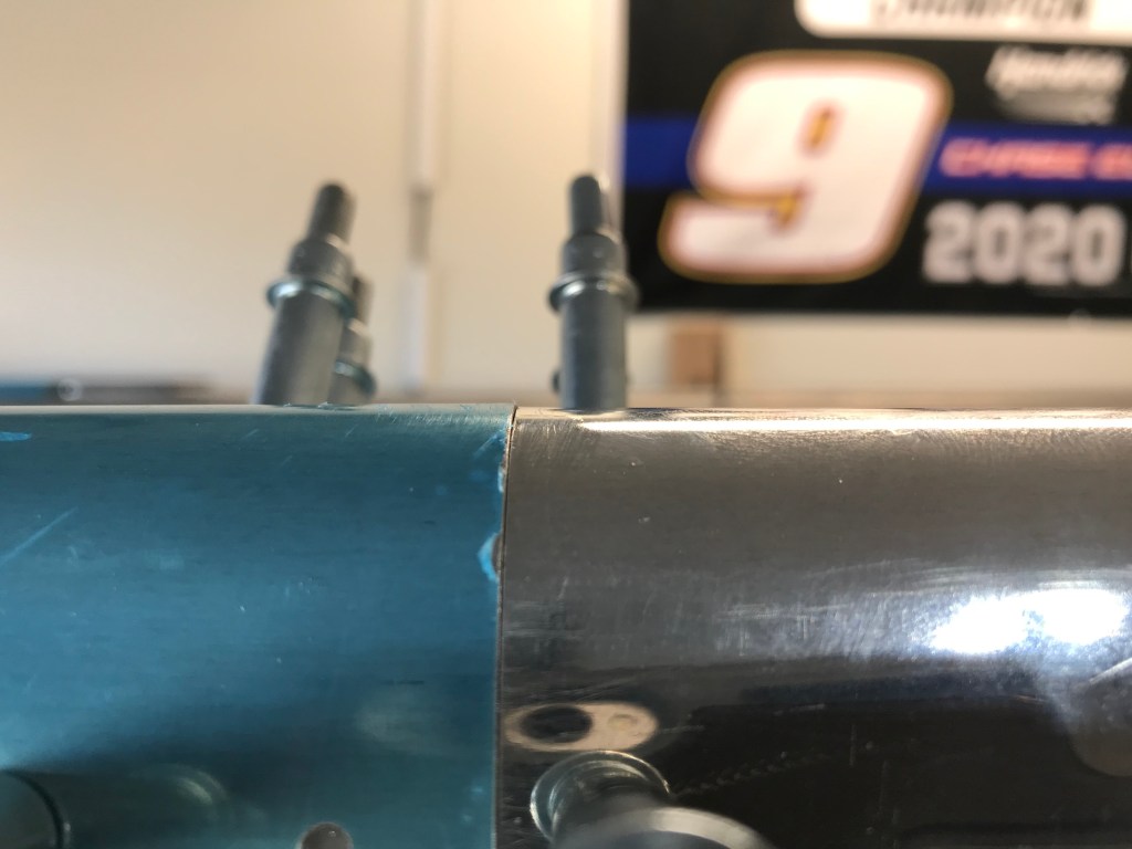
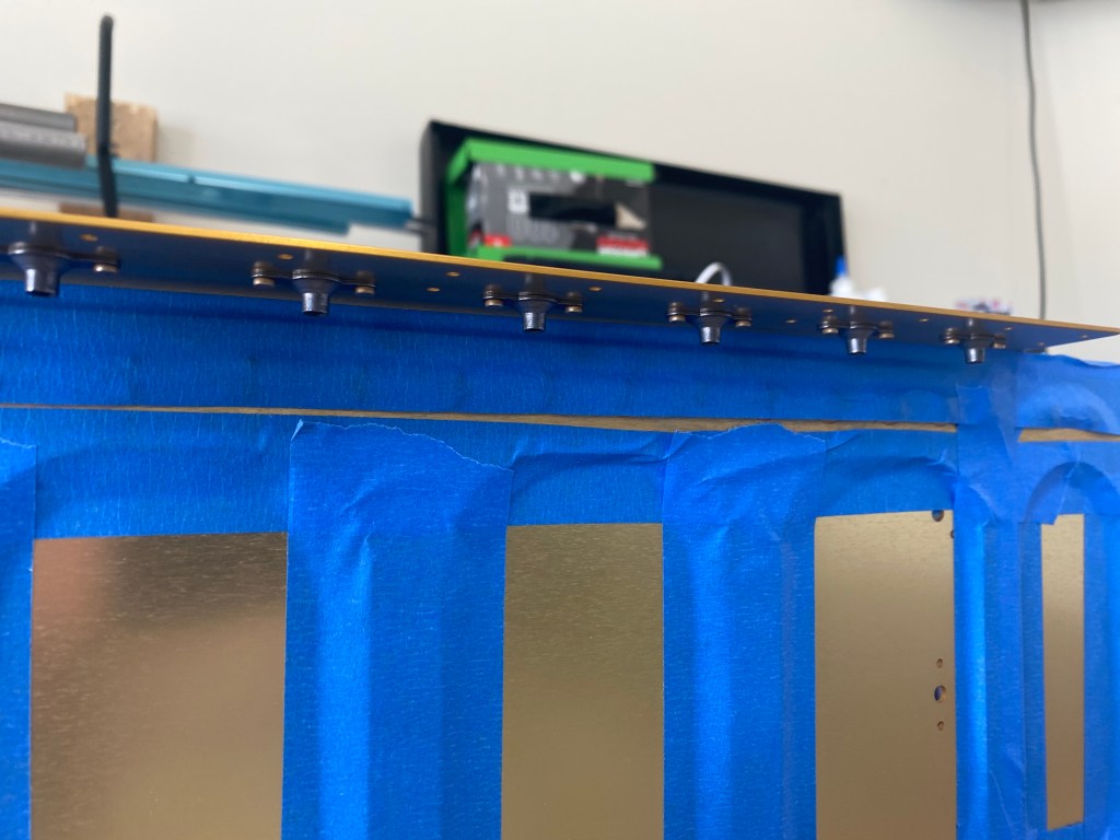
The last little step in attaching the tank for fit, is to drill the attach holes into the “Z” attach brackets. Since you want these to fit perfectly, the center (of three) holes is drilled before going on the spar, but once there the other two are matched drilled. This ensures a perfect fit. Next up will be more fuel tank work!

The Rear Spar

There are two main points where the wings attach to the rest of the plane. The first is the main spar, which we talked about earlier. The second is the rear spar. Just like the main spar, the rear spar attaches to the wing ribs (we will talk more about these later, I promise!). The rear spar also has several doublers for additional brackets to be added. So you can see in the pictures below some of the doublers, and both the left and right rear spars.

The normal process of match and final drill continues. Then remove the blue film, debur, and dimple where needed. At this point, I believe I can debur in my sleep! Since the airplane is symmetric, each side should be a mirror image of each other. While working on the aileron attach doubler, I noticed something did not look right. The two pieces where not a mirror image and I didn’t know why.

I went back and measured a reference mark on both rear spars, the left was one inch longer than the right. I went back to the instructions, and sure enough, the right doubler was positioned one inch off. Off to Van’s to order a replacement part. Valuable lesson learned here: read directions, measure, mark, reread directions, remeasure, step back and make sure it makes sense, then finally after all of that, drill. Luckily all the other doublers turned out great. Next is to prime all the parts.

Finally the rear spar doublers are riveted to the rear spar. This entire section was pretty straight forward. Next will be the wing skeleton structure.

Wing Main Spar

So the first step on the wings is to prepare the main wing spars for several other structures that will be attached to them. This is mainly accomplished by adding nut plates (some people call them plate nuts) to help attach the fuel tanks and inspection panels to the spar. To do this, we have to countersink the flange on the spar for the rivets to hold the nutplates and the screws for the fuel tanks.

I started out by adding painters tape to any gap where metal shavings could fall into. I did not want to have metal shavings fall into a gap. I do not think it would hurt anything, but easier to tape and not worry about it. The I started countersinking the rivet holes that will hold on the nut plates. Not too bad!

Next I coated with holes with a solution that will protect the aluminum and I riveted in the nut plates. There were a total of over 120 of these nut plates (remember I describe the action once, but then I have to repeat on the other wing) that I installed. Overall, very happy with the way they turned out.