
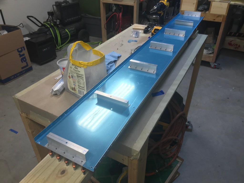
So similarly to the leading edges, the fuel tanks have a skin that is held in shape by a set of internal ribs. There are a few differences between the two. The first is the fuel tanks have additional stiffeners along the bottom of the skins. This are very similar to what was made and used on the rudder and elevators. Next, the ribs have a cutout on the bottom corners. This is to allow fuel to drain to the pickup so it can go to the engine, and it also allows water to drain to the lowest point, which has a quick drain. This drain is checked before every flight to ensure no water is in the fuel. The rest of the assembly went together just like the leading edge.


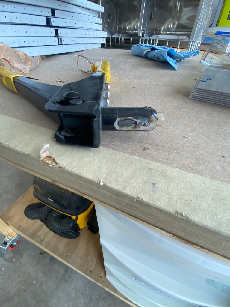
Since the leading edge ribs attach directly to the spar, the fuel tank has to have a back baffle to help create a water-tight tank. The baffle has attach brackets which attach the baffle and tank to the spar. These are made from a “Z” channel that is supplied. Once the tank is together, the attach brackets are temporarily attached to the baffle with blind rivets. The issue is the web of the channel is so close, most rivet pullers do not fit into the area. So, a quick trip to a local tool shop resulted in an inexpensive rivet puller. It was then ground down with a grinding wheel until it fit, and it still functioned! This was then used to pull the rivets, and finish this part of the tank build.

Also, I’m trying something new. I’ve been saving time-lapses of my work to help prove to the FAA that I am the primary builder of this airplane. I have put several parts together in videos, and I plan to start sharing them with the blog posts. So feel free to check them out.

Nice job, Dallas. I know you make your parents proud!
LikeLike